First-time electronics learner
Build a battery-powered LED with a resistor and switch, then change one value at a time.
You learn polarity, current limiting, open circuits, and the difference between a live and interrupted path.
tinkercad circuitsCircuit tutorial
This practical guide shows how to use tinkercad for circuits without guessing where each wire goes. Choose a project path, simulate it, and verify the behavior before touching physical components.
Choose your route
Use the simplest route that matches your goal. A small component test needs a different setup from a programmed Arduino project.
The simulator can represent common parts, but it cannot reproduce every sensor, board revision, tolerance, or damaged component.
WorkaroundChoose a close substitute, record the assumed specifications, then validate the design with the real part.
A simulated voltage or current is useful for learning and debugging, not proof that a manufactured circuit will meet every electrical requirement.
WorkaroundUse a multimeter, oscilloscope, datasheet, and suitable protection when moving to hardware.
A basic circuit simulation cannot stand in for network latency, radio interference, authentication, or a complete connected-device test.
WorkaroundMock the input locally first, then test networking separately on the target board.
Microcontroller simulations are limited to the boards, libraries, and components available in the workspace.
WorkaroundKeep the logic modular and port the sketch to the physical board before finalizing the project.
Path A
Choose this route for LEDs, switches, buzzers, resistors, and other beginner-friendly experiments that do not require microcontroller code.
Create a circuit project and scan the component panel before placing anything. Identify the power source, breadboard, input, output, and any component that limits current.
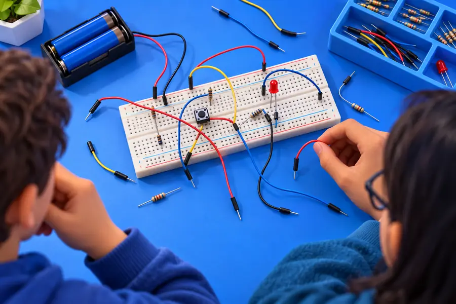
Put the components on the breadboard so the connection points are easy to trace. Join positive and negative rails consistently, then wire one section at a time instead of dragging several leads at once.
Run the circuit, activate switches or other inputs, and watch the output. If the result is wrong, stop the simulation and inspect power, polarity, shared rows, and missing resistance before rebuilding.
Path B
Use this route when an Arduino or another supported controller must read an input and drive an output. The key change is adding code, pins, and a repeatable test condition.
A clean schematic makes code errors easier to separate from wiring errors.
Final check
A simulation is most useful when the result can be explained. Run the same checks every time so a circuit that appears to work is also understandable and reproducible.
Practice projects
These examples give different users a clear first experiment while keeping the same habits: plan the path, connect carefully, simulate, and explain the result.
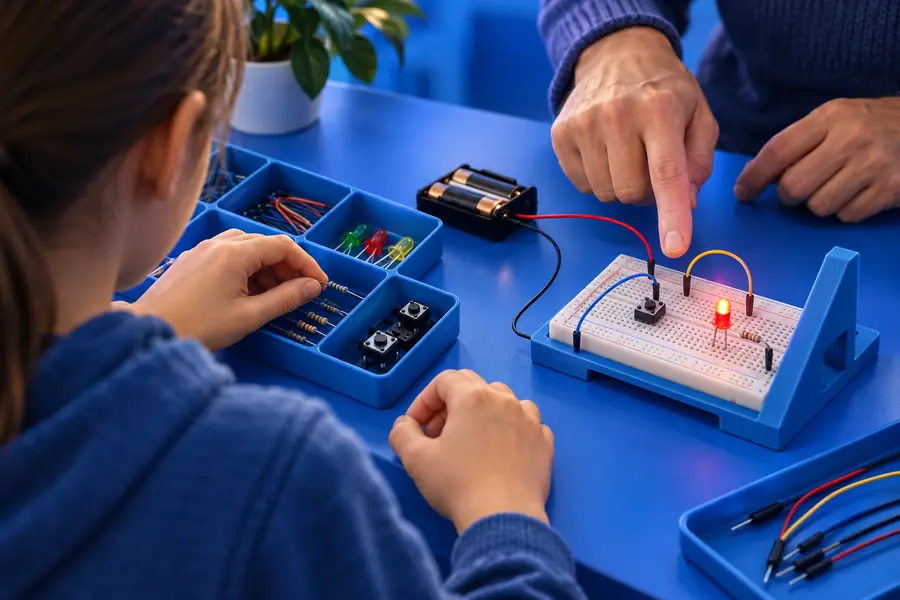
Build a battery-powered LED with a resistor and switch, then change one value at a time.
You learn polarity, current limiting, open circuits, and the difference between a live and interrupted path.
tinkercad circuitsConnect a pushbutton and LED, map the pins, and write a short sketch that changes the LED state.
You separate wiring faults from code faults and gain a repeatable pattern for later projects.
tinkercad arduinoModel the expected circuit first, label the components, and record what should happen at each test point.
Your physical build starts with a testable prediction instead of trial-and-error wiring.
tinkercad for studentsUse a sensor, controller, and output to test the basic decision logic before ordering parts.
You find missing connections and unclear assumptions while the design is still easy to change.
how to use tinkercad for 3d printingSetup comparison
Both routes use the same careful wiring process, but the controller-based version adds software, pin assignments, and logic states.
Basic component circuit
Arduino-controlled circuit
Basic component circuit
Test a direct electrical relationship between components.
Arduino-controlled circuit
Test how code responds to inputs and controls outputs.
Basic component circuit
Power source, breadboard, passive parts, switches, LEDs, or buzzers.
Arduino-controlled circuit
Controller board plus inputs, outputs, power, and supporting components.
Basic component circuit
No code for a direct on/off behavior.
Arduino-controlled circuit
A sketch is needed to read pins and make decisions.
Basic component circuit
Polarity, continuity, resistance, power, and shared breadboard rows.
Arduino-controlled circuit
All basic wiring checks plus pin numbers, syntax, timing, and logic states.
Basic component circuit
LED with resistor, switch-controlled lamp, or buzzer.
Arduino-controlled circuit
Button-controlled LED, traffic light, sensor reading, or servo movement.
Basic component circuit
How current paths and component connections affect visible output.
Arduino-controlled circuit
How hardware inputs, software conditions, and output signals work together.
Basic component circuit
Real voltage limits, component tolerances, heat, and physical assembly.
Arduino-controlled circuit
Board compatibility, library behavior, timing, power delivery, and real sensor noise.
Tutorial FAQ
These answers address common questions people ask when beginning a circuit project in the workspace.
Open the Circuits workspace and create a new circuit. Begin with a small goal, such as lighting an LED or reading a button, then place only the parts needed for that test.
Choose a circuit goal, place the power source and components, connect the rails and signal paths, and start the simulation. Check one behavior at a time, stop when the result is unexpected, and inspect polarity, pin mapping, and shared breadboard rows.
An LED, resistor, battery, and switch is a strong first project because the expected behavior is easy to see. After that, add an Arduino and button so you can compare direct wiring with code-controlled output.
Yes, it can help you practice pin connections, simple sketches, inputs, outputs, and debugging before assembling hardware. Treat the simulation as a learning and planning step, then confirm the design with the exact board and components you will use.