Arduino circuit lab
Build and test with tinkercad arduino
Tinkercad Arduino projects let you place components, write sketches, and test circuit behavior in a browser before connecting physical hardware. Follow one complete workflow from blank workspace to simulated output.
Before you begin
Prerequisites
A small amount of preparation makes the Arduino workflow clearer and helps you separate wiring mistakes from code mistakes.
-
1
Choose a simple goal
Start with one visible result, such as turning an LED on with a button or changing its brightness with a potentiometer. A narrow goal gives you fewer wires and fewer possible causes when something fails.
-
2
Know the essential parts
For a first project, use an Arduino Uno, a breadboard, an LED, a resistor, and either a button or potentiometer. Learn the difference between power, ground, digital pins, and analog input before adding sensors.
-
3
Prepare the sketch logic
Decide which pin is an input and which pin is an output. In code, that usually means setting pin modes in setup, reading or checking a value in loop, and writing a result to the chosen output.
Keep exploring
One full run-through
Use this route as a starting point, then move into related Tinkercad workflows when your project needs more modeling, circuit detail, or Arduino-specific practice.
Choose your setup
Options table
These common choices affect how much wiring, code, and physical behavior your simulated Arduino project can represent.
Beginner LED project
Interactive sensor project
Main purpose
Beginner LED project
Learn output control with a visible light
Interactive sensor project
Read an input and respond with an output
Typical components
Beginner LED project
Arduino Uno, LED, resistor, wires
Interactive sensor project
Arduino Uno, sensor or potentiometer, output device, wires
Code pattern
Beginner LED project
Set an output pin HIGH or LOW
Interactive sensor project
Read an input, compare a value, then choose an output
Wiring difficulty
Beginner LED project
Low; fewer connections and fixed values
Interactive sensor project
Moderate; power, ground, signal, and component orientation matter
Best first result
Beginner LED project
An LED turns on, off, or blinks
Interactive sensor project
An LED, buzzer, or motor response changes with input
Main debugging focus
Beginner LED project
Pin numbers, polarity, resistor placement
Interactive sensor project
Input range, threshold logic, grounding, and changing readings
Good next step
Beginner LED project
Add a button or change the blink timing
Interactive sensor project
Display a reading, smooth input, or control two outputs
See the workflow
Options table: from wiring to simulation
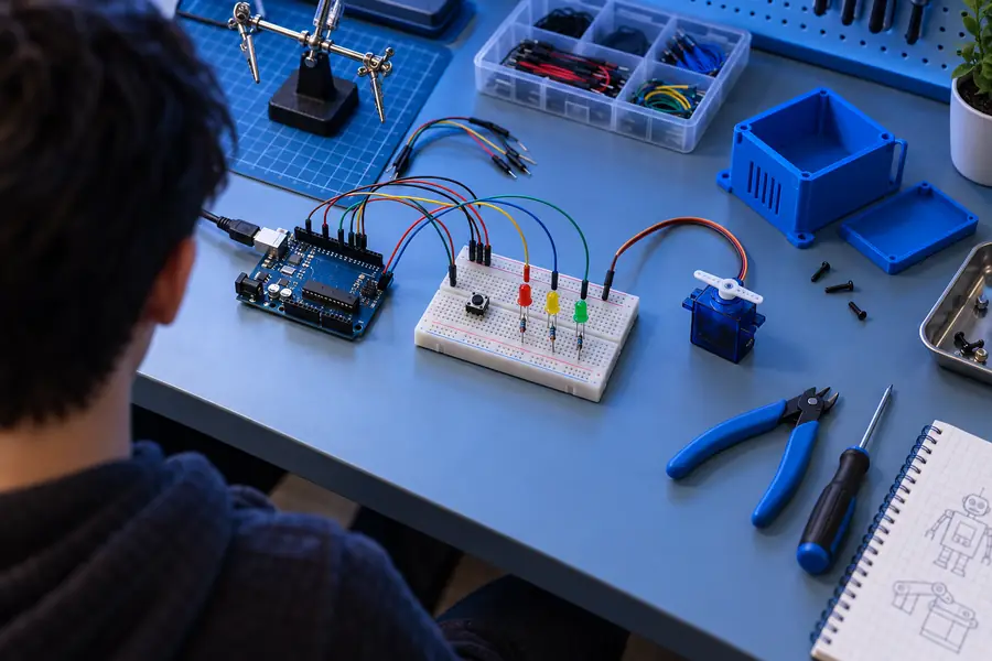
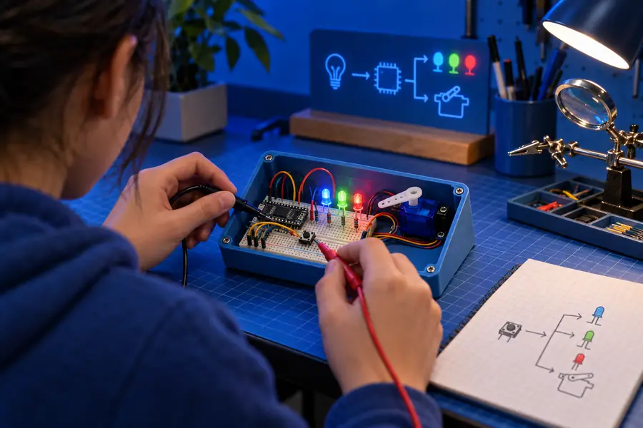
A successful Arduino build moves from a readable circuit layout to a verified simulation. The difference is not visual polish alone; the code and connections must agree.
- Wire and configure
- Run and verify
Start with the simplest circuit that proves one behavior, then add components only after the first simulation works.
Debug honestly
What fails
A Tinkercad Arduino simulation is useful for learning and checking logic, but it cannot remove every electronics problem or guarantee that a physical build will behave identically.
-
It cannot model every real-world hardware issue
The simulator may not represent noise, loose jumper wires, damaged parts, battery behavior, or every electrical limit found on a physical breadboard.
WorkaroundUse the simulation to validate logic, then check voltage, current, polarity, and connections with real hardware precautions.
-
It cannot fix mismatched pin numbers
Code can compile while controlling the wrong pin. An LED on one digital pin will not respond correctly if the sketch writes to another.
WorkaroundLabel the wiring plan and keep pin constants together near the top of the sketch.
-
It cannot replace component datasheets
A simulated sensor or module may expose simplified behavior compared with a specific physical part, library, or breakout board.
WorkaroundAfter the virtual test, compare the real component's pinout, voltage range, library requirements, and wiring diagram.
-
It cannot make complex code easy to debug
Long sketches, nested conditions, and several interacting inputs can still produce confusing results even when the circuit is wired correctly.
WorkaroundTest one function at a time, use Serial Monitor output, and add components in small, verifiable stages.
Your questions
FAQ
These answers cover the practical role of Arduino projects in Tinkercad and what the workspace is best suited to demonstrate.
You can use Tinkercad to create browser-based 3D designs and simulate electronic circuits, including Arduino projects. For Arduino work, it is especially useful for practicing wiring, writing sketches, and observing basic input and output behavior before using physical components.
Yes. Tinkercad includes an Arduino Uno model that can be connected to virtual components and controlled with Arduino-style code. You can run the simulation, inspect the result, and revise the circuit or sketch without assembling hardware first.
Beginner projects with clear inputs and outputs work best, such as blinking LEDs, button-controlled lights, potentiometers, buzzers, and simple sensor responses. These projects make it easy to compare the wiring, pin assignments, and code logic.
No. It demonstrates the logic and many basic connections, but it does not reproduce every physical condition. Real builds still require attention to component ratings, power limits, pin availability, wiring quality, and the exact hardware model.